Read it in order. The order matters more than you'd think. You'll need the PARTS list to hand.
STEP 1 — Weld the frame
Cut your steel angle into a 600mm square base with four uprights. Box it. Brace the corners. It carries about 40kg of copper and it CANNOT flex when she's running or your field goes lopsided and you'll punch a hole in the wrong place (ask me how I know — new shed wall, October). Grind your welds flat where the coils sit. Paint it if you want, I never.
STEP 2 — Wind the coils
This is the part folks get wrong, so listen up, I'm gonna be thorough. You want TWO flat spiral "pancake" coils. Start at the centre eyelet, keep the wire TIGHT, lay each turn snug against the last, no gaps, no crossing over. I count 118 turns per coil — if you lose count START AGAIN, do not guess. Every fourth turn, lay a bead of clear lacquer and let it tack, or the whole thing buzzes loose at voltage and unwinds itself into a bird's nest (lost a whole Saturday to that). Leave 18 inches of tail on each end. When you're done you'll have two copper records about the size of a bin lid. Bake 'em low (~60°C, oven OFF and door cracked) for an hour to set the lacquer. Let cool. Do not rush this. The coils are the only part where being neat is the whole job.
STEP 3 — Set the coils in place (NEW PICS!)
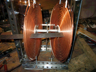
Mount the two coils facing each other, dead parallel, on the uprights. The gap between them is the chamber, and the gap matters to the millimetre. I run mine at exactly 41mm, shimmed with nylon washers — NOT metal, metal shorts it and you'll know about it. Get them coplanar: lay a steel rule across both faces and sight down it, both ways, like checking a shelf is level. If one coil is even a degree off, the field cones instead of focuses and the whole rig is just an expensive way to give yourself a sunburn. Bolt them down with NYLON bolts. Tighten in a star pattern. Re-check the gap after tightening because tightening moves things. Then check it again tomorrow. I am not kidding.
STEP 4 — The chamber & the pump
Centre your glass jar in the gap (it sits IN the 41mm, that's why the gap is what it is). Seal the lid with a rubber gasket and a port for the vacuum line. Run the pump down until the jar "pings" and the gauge holds. You want it good and empty — air in there just makes purple sparks and ozone and a headache. A little glow is fine. A lot of glow means you've got a leak, find it with soapy water like a gas man.
STEP 5 — The oscillator bank
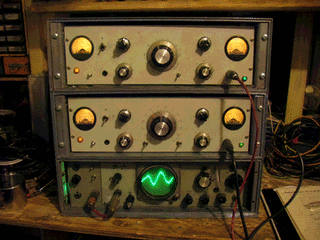
Wire each oscillator to one coil through the HV transformer (this is where the microwave guts earn their keep). The left rack sets the carrier, the right rack sets the shape. You drive the two coils slightly out of step so the field "rotates" in the gap — that's the bit that does the work. Watch it on a little ’scope. When the trace settles into a clean standing pattern and stops jittering, you are CLOSE.
STEP 6 — Dial in the frequency
STEP 7 — Load the timing software
STEP 8 — Power up
Tinfoil hat ON (I'm serious, the field finds the wettest thinking in the room and that's your head). Stand to the SIDE, never the front. Bring the HV up over about thirty seconds. The jar will glow, then go clear — clear like a window, not like glass — and that's your aperture. It is small. Mine is about the size of a saucer. Do not put your hand in it. Put a 2p in it. See where the 2p goes.
STEP 9 — see what happens next » RESULTS